Nero Robot Arm Documentation
Document Version: V1.0.0

Version Update Description
|
|
|
|
|
|
|
|
|
|
|
|
|
|
Important Safety Information
This chapter contains crucial safety instructions. Any individual or organization must read and understand this information before using the device, especially before powering it on for the first time. It is essential to follow all assembly instructions and guidelines provided in this manual. Pay special attention to the text with warning signs. Before using the Nero device, be sure to read the NERO User Manual. For any questions regarding usage, please contact us at support@autodiscovery.co.uk.
Warning: ⚠ This indicates a potentially hazardous situation. Failure to avoid it may result in personal injury, property damage, and severe equipment damage.
WARNING ⚠: Autodiscovery shall not be liable for any damage caused by a robotic arm that has been damaged, altered, or modified in any way. Autodiscovery shall not be held responsible for any damage to the robotic arm or other equipment arising from program errors or non-standard operations.
Limitation of Liability: By using this robotic arm, you acknowledge that you have read, understood, and accepted all terms and content of this user manual and safety information. The user undertakes full responsibility for their actions and all resulting consequences. The user agrees to use the robotic arm solely for legitimate purposes and complies with these terms as well as any related policies or guidelines established by Autodiscovery. During operation, strictly adhere to all requirements, including but not limited to the user manual and safety information. Autodiscovery shall not be liable for personal injury, accidents, property damage, legal disputes, or conflicts of interest caused by non-compliance with usage instructions or unavoidable factors. This robotic arm is not suitable for use by individuals under 18 years of age or those without full civil capacity. Please prevent such individuals from accessing this product, and exercise extra caution when operating the device in their presence.
The information in this manual does not cover the design, installation, and operation of a complete robotic arm application, nor does it include all peripheral equipment that may affect the safety of the complete system. The design and use of the complete system must comply with safety requirements specified in the standards and regulations of the country where the robotic arm is installed.
Integrators and end-users of the robotic arm are responsible for ensuring compliance with relevant regulations and applicable laws, and for ensuring that no significant hazards exist in the complete robotic arm application.
This includes but is not limited to the following:
1 Validity and Responsibility
- Conduct a risk assessment of the complete robotic arm system.
- Integrate additional safety devices for machinery as defined in the risk assessment.
- Verify the accuracy of the design and installation of the entire robotic arm system, including software and hardware components.
- Integrators and end-users must conduct safety assessments in accordance with relevant regulations and applicable laws for all functions related to this robotic arm, ensuring no significant hazards or safety risks exist in practical applications.
- Be aware of potential safety risks before operating and using the equipment.
- Ensure that users do not modify any safety measures.
- Collect all documents in the technical files, including the risk assessment and this manual.
2 Environment
- Read this manual carefully before first use to understand the basic operation content and specifications.
- Use the robotic arm in a relatively open area. The robotic arm is not equipped with any automatic obstacle avoidance or sensing sensors.
- Operate within an ambient temperature range of -20℃ to 50℃.
- Unless customized with a specific IP rating, the robotic arm has an IP22 rating for dust and water resistance.
3 Inspection
- Ensure the robotic arm has no obvious abnormalities.
- Verify that all wire connections are secure during use.
4 Operation
- Maintain a clear and unobstructed area around the robotic arm during operation.
- Operate the robotic arm within the line of sight.
- The maximum payload capacity of the robotic arm is 3KG. Ensure the effective load does not exceed this limit during use.
- Immediately stop using the device if any abnormality occurs to avoid secondary damage.
- Contact relevant technical personnel if the device malfunctions. Do not attempt to handle the issue without authorization.
- Use the device in an environment that meets the requirements of its IP rating.
5 Usage Warnings ⚠
- Ensure the robotic arm and tools/end-effectors are always correctly and securely fastened in place.
- Wear safety goggles and protective equipment when entering the robotic arm's workspace is unavoidable.
- Ensure the robotic arm has sufficient space for unrestricted movement.
- Ensure safety measures are established as defined in the risk assessment.
- Do not wear loose clothing when operating the robotic arm. Tie long hair back before the operation.
- Do not use the robotic arm if it is damaged or shows any signs of abnormality.
- If the host computer software displays an error message, perform an emergency stop immediately and contact technical personnel.
- Ensure that people keep their heads, faces, and other body parts outside the reach of the robotic arm during operation or before starting the operation.
- Do not modify the robotic arm. Modifications may lead to unpredictable hazards for integrators.
- Do not expose the robotic arm to permanent magnetic fields. Strong magnetic fields may damage the robotic arm.
- The robotic arm generates heat during operation. Do not handle or touch the robotic arm while it is operating or immediately after stopping, as prolonged contact may cause discomfort. Disconnect the power supply and wait for one hour for the robotic arm to cool down completely.
- Connecting different machinery may increase hazards or create new ones. Always conduct a comprehensive risk assessment of the entire installation. Different functional safety levels may apply based on the risk assessment; therefore, always select the highest performance level when different safety and emergency stop performance levels are required. Always read and understand the manuals of all equipment used in the installation.
- This robotic arm is not suitable for use by individuals under 18 years of age or those without full civil capacity.
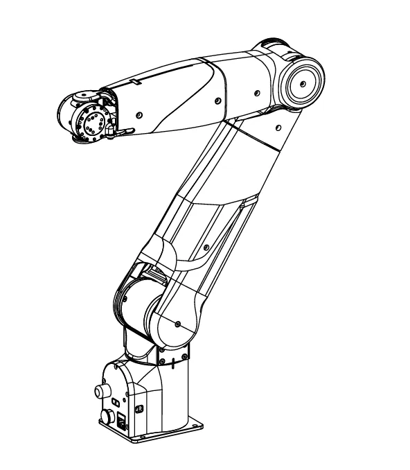
1 Robotic Arm Overview
This 7-degree-of-freedom (DOF) robotic arm is specially designed for the education and research industry, consumer application scenarios, and industrial automation. It has a payload capacity of 3kg and is suitable for various scientific research and industrial applications, such as humanoid robots, automatic assembly, and automatic handling. The 7 joints provide comprehensive operational flexibility, ensuring high precision and repeatability. The robotic arm adopts a modular design for easy maintenance and upgrades. It provides an intuitive user interface that simplifies programming and operation processes, enabling even non-professionals to get started quickly. It can be widely used in scientific research, education and teaching, automobile manufacturing, electronic assembly, food processing, laboratory automation, and medical equipment operation.
1.1 Product List
|
|
|
|
|
|
|
|
|
|
|
|
|
|
|
|
|
|
|
|
|
1.2 Performance Parameters
|
|
|
|
|
|
|
|
|
|
|
|
|
|
|
|
|
|
|
|
|
|
|
|
|
|
|
|
|
|
|
|
|
|
|
|
|
|
|
|
|
|
|
|
|
|
|
|
|
|
|
|
|
|
|
|
|
|
|
|
|
|
|
|
|
|
|
|
|
|
|
|
|
|
|
|
Note: The above data are test results of Agilex robotic arms in a controlled test environment. Results may vary under different environments and usage conditions; please refer to actual experience.
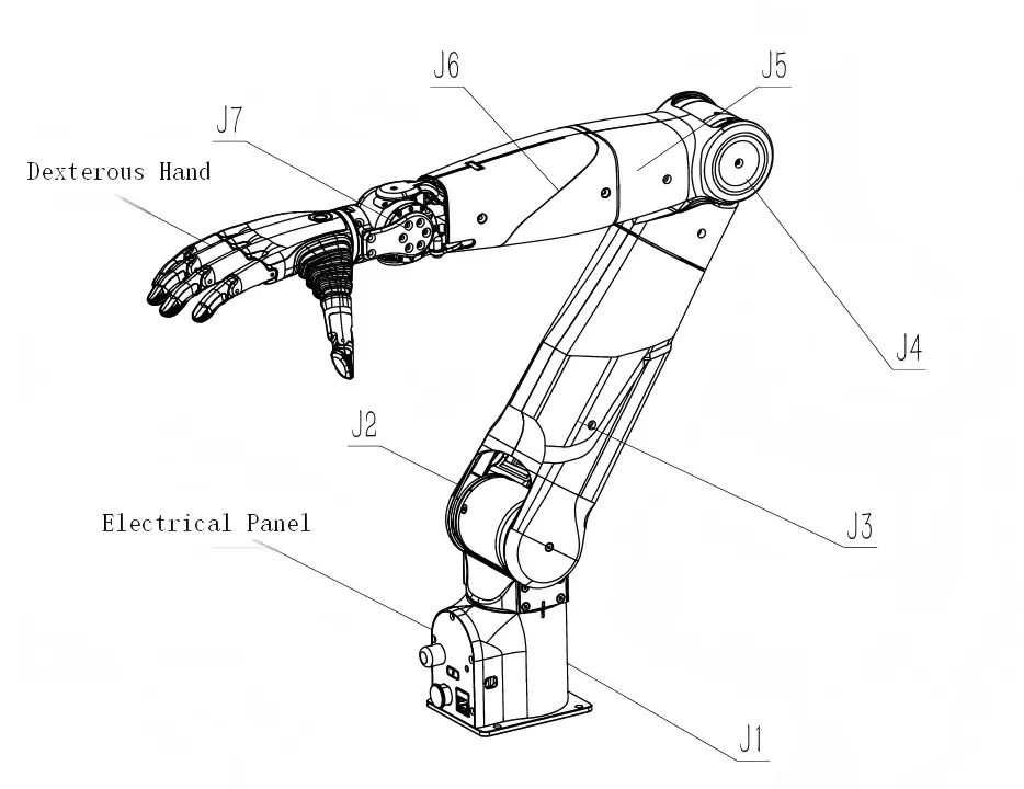
2 Basic Introduction
This robotic arm features 7 degrees of freedom and a 3kg end-effector payload. The seven rotating joints provide comprehensive operational flexibility, ensuring high precision and repeatability. It adopts a lightweight design, enabling the robotic arm to achieve fast movement while maintaining a high load capacity. It can be widely used for real-scenario data collection in embodied intelligence research.
2.1 Electrical Interface
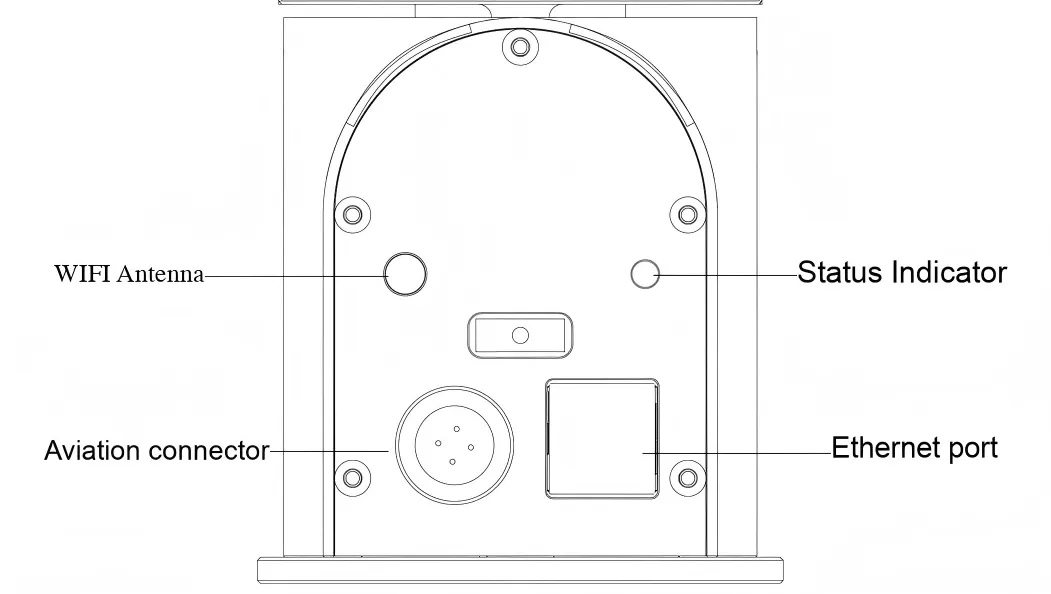
2.1.1 Electrical Panel Introduction
The robotic arm base panel is equipped with an aviation connector, a standard Ethernet port, a WIFI antenna, and status indicator lights. The aviation connector contains two sets of lines: one for power supply to the robotic arm and one for CAN communication between the upper system and the robotic arm.
Electrical Panel Status Light Indication
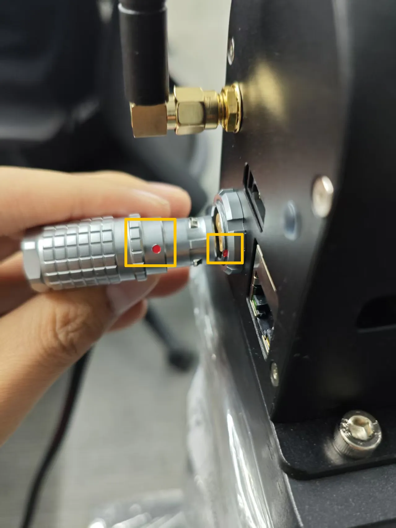
Note: Align the red dot on the base panel with the red dot on the cable. The textured part of the aviation connector is a retractable area under force. For insertion, align the red dots and insert directly. For pulling out, press the textured part and pull out.
2.1.2 End-Effector Connection Description
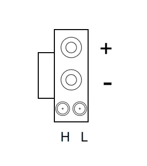
The end joint reserves an XT30 2+2 interface, with power and CAN definitions shown in the figure below. The voltage is 24V, with a maximum current of 2A. The end-effector CAN communication only supports AgileX's own devices. Unauthorized connection of other CAN devices is strictly prohibited, as it may cause uncontrollable damage.
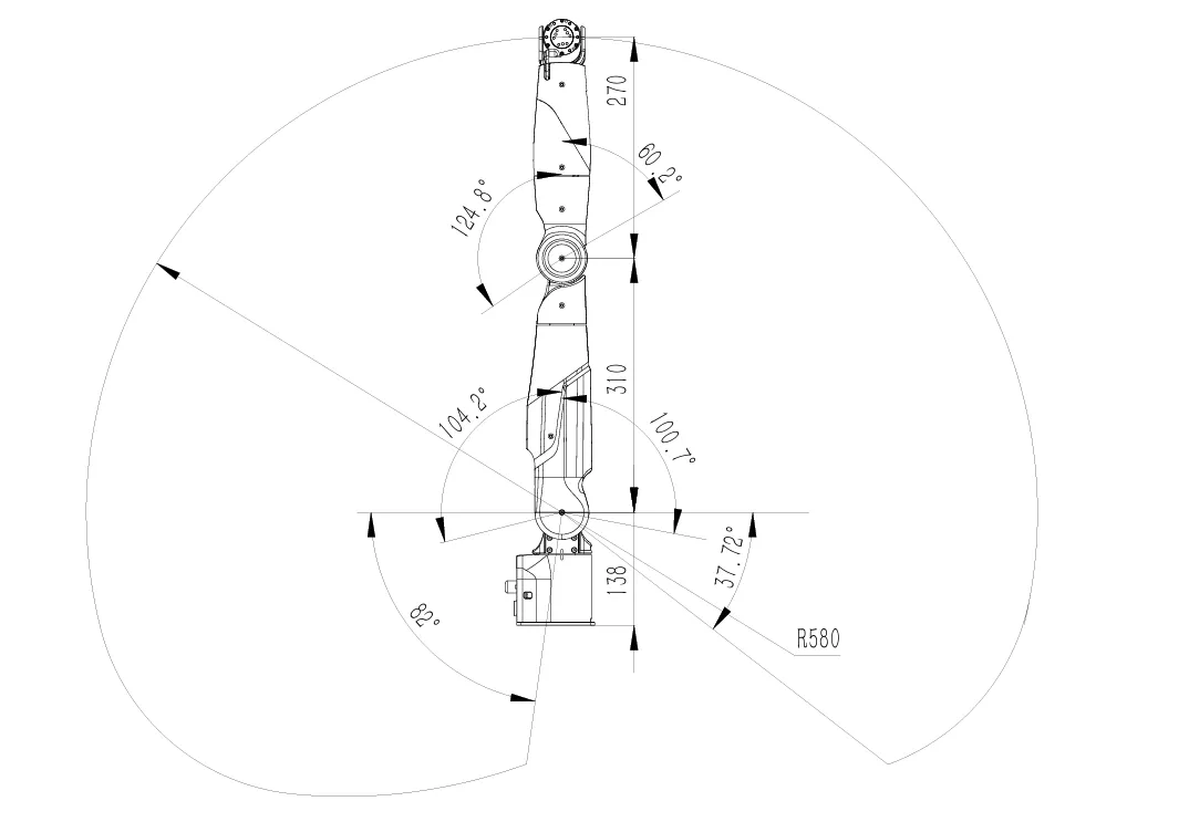
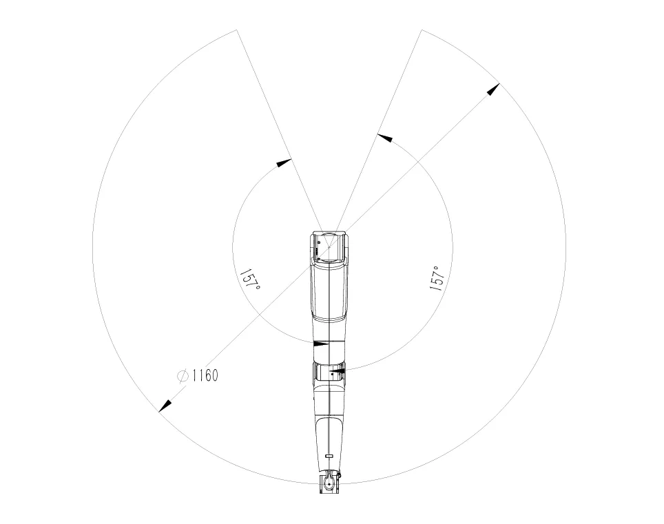
2.2 Robotic Arm Workspace and Payload
This chapter clearly defines the motion space boundaries and joint movement ranges of the robotic arm through kinematic diagrams, providing a basis for users to design workstation layouts, plan trajectories, and implement safety protection measures.
2.3 Mechanical Installation Instructions
2.3.1 Base Mounting Instructions
The robotic arm base is fixed with screws. The base has 4 pre-reserved M5 threaded through holes, and 4 M5 screws are included in the accessory package. The included hexagon tool can be used for installation. The hole spacing is 70mm. If you are designing an adapter structure for mobile equipment or fixed platforms, you can make the hole positions with a 70mm spacing.
Base Mounting Diagram
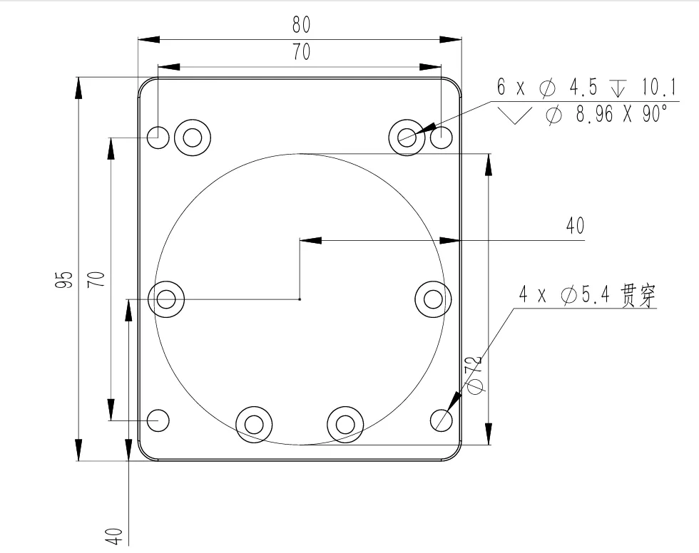
2.3.2 End-Effector Installation Instructions
Dexterous Hand Installation
1Secure the robotic arm to the installation platform. Take out the dexterous hand, flange accessories, including the flange and accessory bolts.
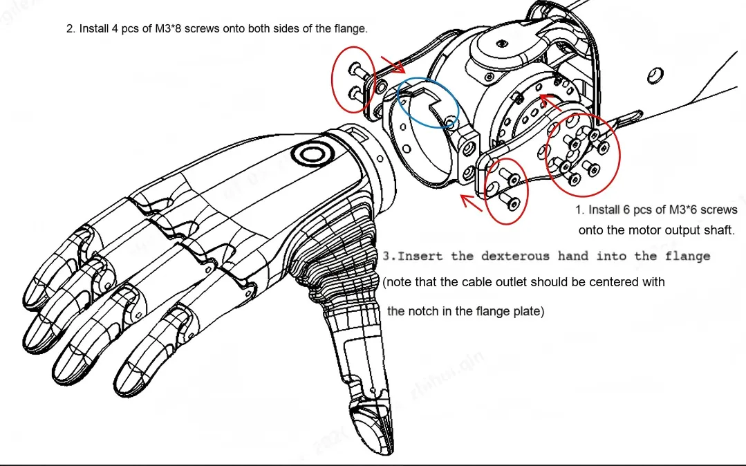
2Install the flange plate as shown in the diagram:
aUse 6 M3×6 hexagon socket countersunk head bolts to mount the baffle to the motor output shaft.
bUse 4 M3×8 hexagon socket countersunk head bolts to fix the flange on both sides of the baffle.
cInsert the dexterous hand into the flange plate (ensure the cable outlet is aligned with the gap in the flange plate).
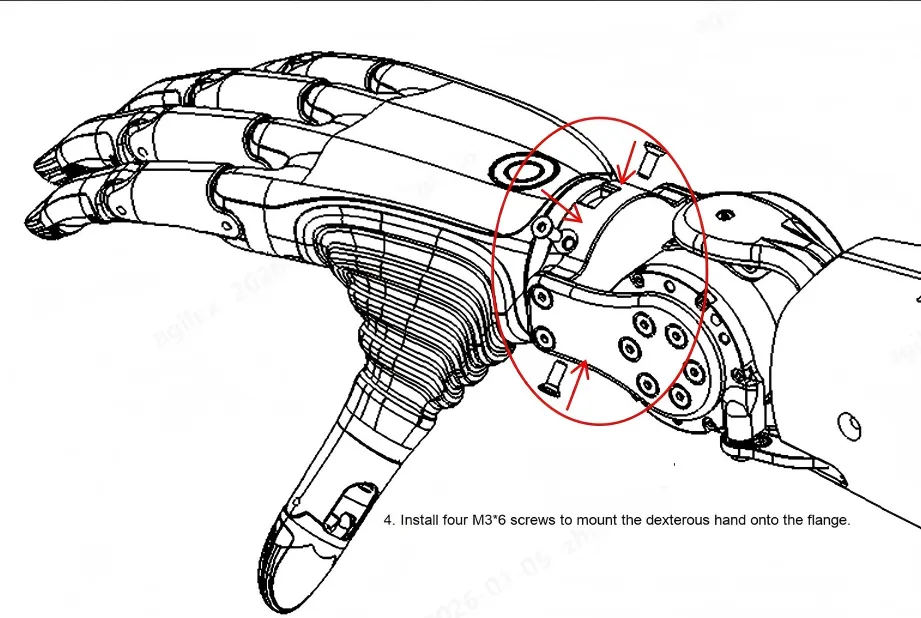
d. Install four M3×6 screws to mount the dexterous hand onto the flange.
3After installing the dexterous hand, connect the power and communication cable from the accessory package to the J6 end interface and the interface on the gripper teach pendant.
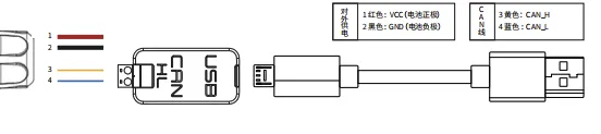
4Connect the aviation cable to the robotic arm. Connect the USB-to-CAN module to the aviation cable by matching CAN-H to yellow and CAN-L to blue. Plug the USB cable of the USB-to-CAN module into the computer. Connect the aviation cable to the adapter and power on the adapter.
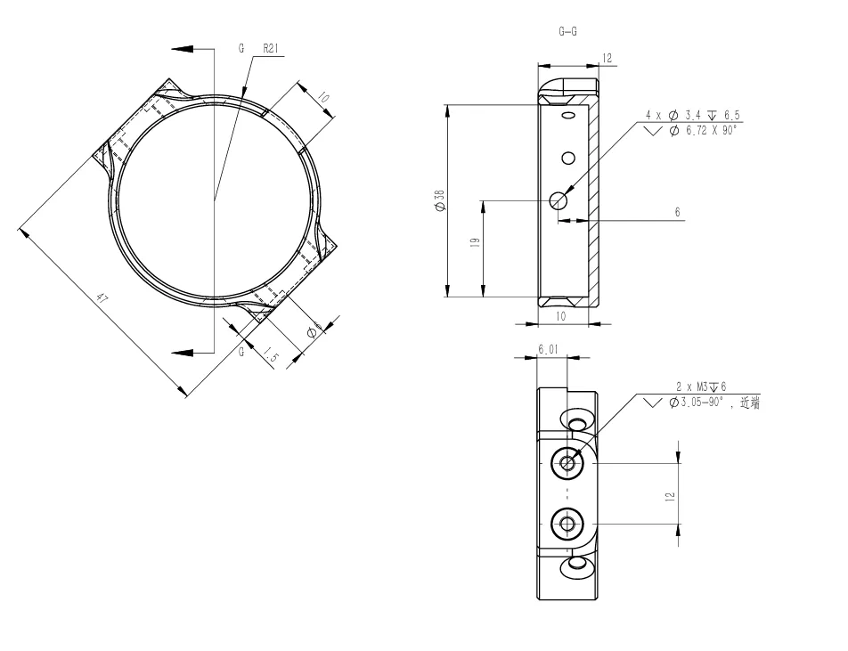
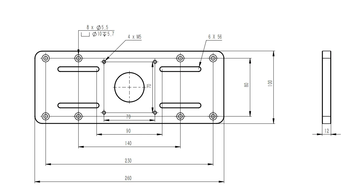
2.3.3 Installation Instructions on Desktop
The desktop installation module is an optional accessory and is not included with the standard product. Dimensions are shown in the figure below. Ensure the module is securely fixed before using the robotic arm.
3 Robotic Arm Operation
3.1 CAN cable connection
Find the CAN cable from the aviation connector. Connect CAN_H and CAN_L in the CAN cable to the CAN_TO_USB adapter, respectively. Connect the CAN_TO_USB adapter to the USB port of the laptop. Refer to the connection diagram for details.
Note: If a non-standard charger is used, the input power supply must not exceed 26V, and the current must be at least 10A.
3.2 Power-On Instructions
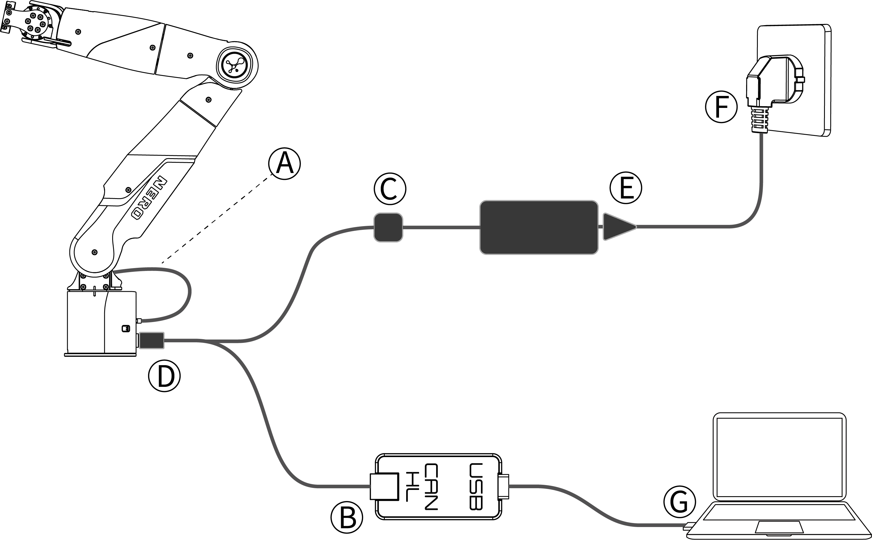
Follow the steps below for the first power-on of the robotic arm:
1Connect the CAN cable of the aviation connector to the CAN_H and CAN_L terminals of device B, respectively.
2Align and insert the XT30 foolproof connector of device C.
3Align the red dot of the aviation connector D with the red dot of the aviation socket on the arm base and insert it.
4Plug the adapter E into the mains power supply.
5Check and confirm that the AC plug F of adapter E is properly connected and powered on. Wait until the indicator light on the electrical panel of the robotic arm base flashes green.
6Insert the USB cable G into the computer to start using the robotic arm.
Note: Align the red dot with the red dot on the cable below. The textured part of the aviation connector is a retractable area under force.
3.3 DH for robotic arm
|
|
|
|
|
|
|
|
|
|
|
|
|
|
|
|
|
|
|
|
|
|
|
|
|
|
|
|
|
|
|
|
|
|
|
|
|
|
|
|
|
|
|
|
|
|
|
|
4 Robotic Arm Connection
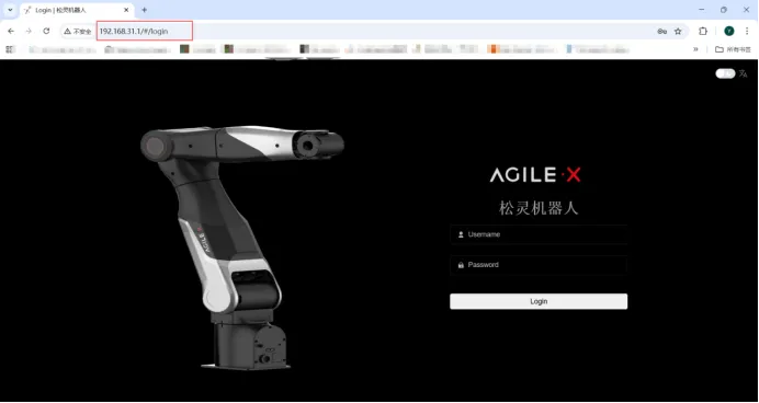
4.1 WIFI connection
WIFI name:agx-7ax-xx WIFI password:12345678
Backend IP Address for Login : http://192.168.31.1/,
Web Login Username: admin Web Login Password: 123456
4.2 Ethernet Connection
Connect the controller to the computer via an Ethernet cable. Connect one end of the cable to the controller's network interface and the other end to the computer's or local area network's network interface. If the connection is successful, the Ethernet port indicator light will flash frequently. The default IP address of the robotic arm controller is 10.90.0.150. For communication with the robotic arm, the IP addresses of all computers must be in the same network segment as the robotic arm controller.
5 Web-Based Host Computer Introduction
5.1 Page Introduction
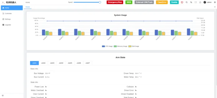
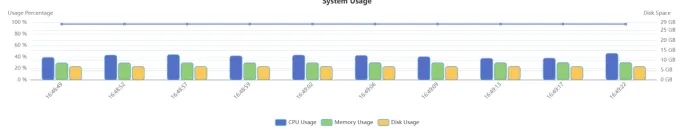
5.1.1 System Usage Rate
The robotic arm has a built-in control board. The system usage rate displays the disk, CPU, and memory usage of the main board. This control board is not open to users.
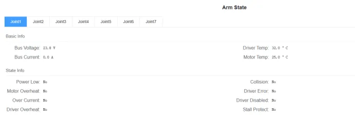
5.1.2 Robotic Arm Status
Displays the status of each joint motor of the robotic arm.
5.1.3 Top Function Button Description
|
|
|
|
|
|
 |
|
|
|
 |
|
|
|
 |
|
|
|
 |
|
|
|
 |
|
|
|
 |
|
|
|
 |
|
|
|
 |
|
|
|
 |
|
|
|
 |
|
|
|
 |
|
6 User Control Area
6.1 Motion Control
|
|
|
|
|
|
|
|
|
|
|
|
|
|
|
|
|
|
|
|
|
|
|
|
Note: If the prompt "Please configure the correct control mode" appears during web interface control, it indicates that the system is not in web control mode. Click the "WEB" button at the top of the interface to switch to web control mode.
6.2 Drag Teaching
Click to add a new teaching program, enter the teaching name, and confirm it. Then click Add in the operation panel — the robotic arm will then enter the gravity compensation mode, allowing you to manually drag the arm to move. After completing the recording, click Pause to end the process.

6.3 Dexterous hand
(Wa)
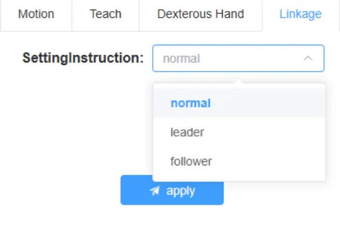
6.4 Coordinated control
The core function of this interface is to set and switch the operating modes of the operating modes of the robotic arm.
normal: This is the independent operating mode. When this mode is selected, the robotic arm(or the control unit)will not participate in any leader-follower coordination and will operate as an independent unit.
leader: This is the master control mode. Designate the currently controlled robotic arm as the "leader unit". In the leader-follower mode, the leader arm is responsible for leading the movement and is used to drive the 'follower arm'.
follower: This is the follower control mode. Designate the currently controlled robotic arm as the 'follower unit'. The follower arm will follow the motion commands of the leader arm in real time to achieve precise synchronous movement.
Note: When using the leader-follower arms, do not set both robotic arms to follower arm mode simultaneously, and do not enable CAN push at the same time when the two robotic arms are connected. Otherwise, it will cause abnormal external network CAN communication. If this happens, the device needs to be restarted.
6.5 Speed Regulation
In the speed adjustment interface, you can drag the progress bar to adjust the percentage of the overall speed of the robotic arm.
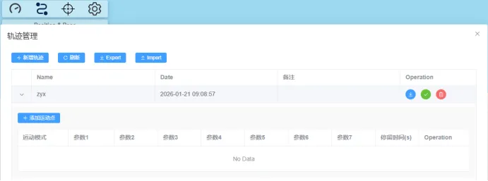
6.6 Trajectory
Trajectory Management is a core control interface that integrates the creation, management, execution, and storage of robotic arm motion trajectories. Through this interface, users can conveniently plan a continuous path composed of multiple "motion points", as well as save, retrieve, and batch-process the path.
Includes Buttons:
●New Trajectory: Create a new blank trajectory.
●Refresh: Refresh the trajectory list below to obtain the latest data.
●Export: Export the selected trajectory file to the local device for backup or sharing.
●Import: Import existing trajectory files from the local device for quick loading and use.
6.7 Set Zero Point
After long-term operation of the robotic arm, the zero position of the arm may deviate due to various factors, such as mechanical wear. When the zero position of the robotic arm joints deviates, we need to recalibrate the zero position of the joints in the Zero Point Setting section of the control panel. This calibration is divided into two methods: manual zero point setting and automatic zero point setting.
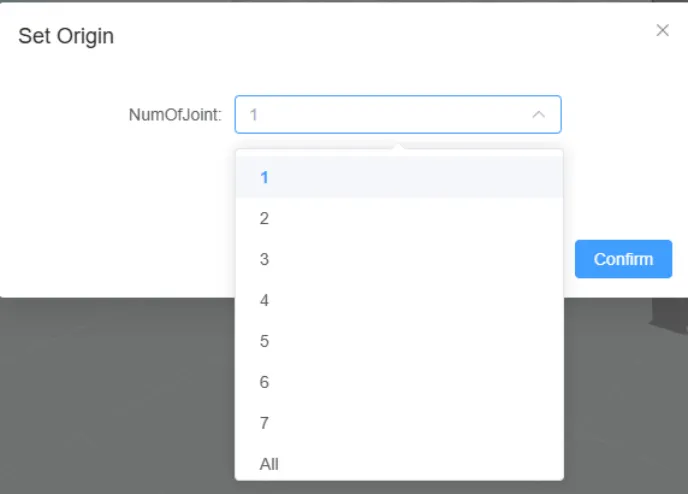
6.7.1 Auto Set Zero Point
For Auto Set Zero Point, you can select a specific joint, choose Auto Set, and click Confirm.
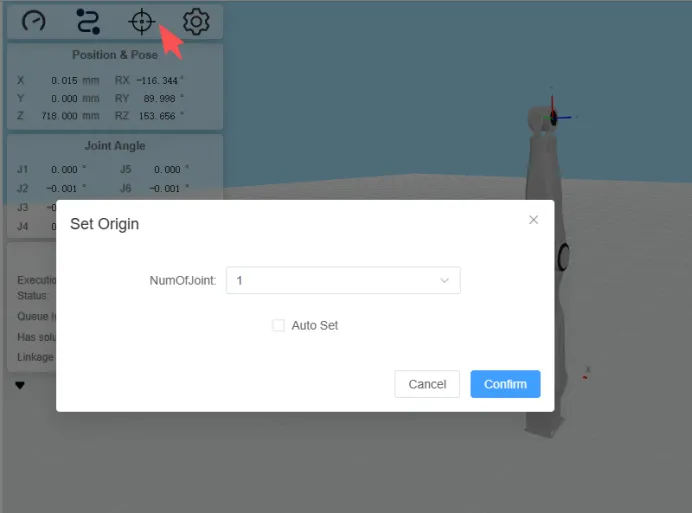
6.7.2 Manual Set Zero Point
For Manual Set Zero Point, you can select a specific joint, disable the joint, then rotate it manually to the zero position and click Confirm.
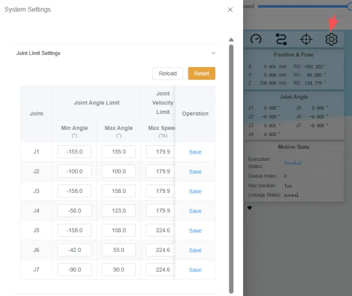
6.8 System Settings
6.8.1 Joint Limit Settings
This interface allows users to precisely define the motion range and maximum allowable speed of each joint of the robotic arm according to practical application scenarios. This prevents the robotic arm from performing hazardous movements due to program errors, misoperations, or unexpected interference, which may result in equipment collision, overload, or damage. To reset the original settings, simply click Reset.
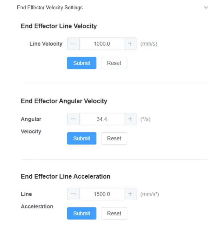
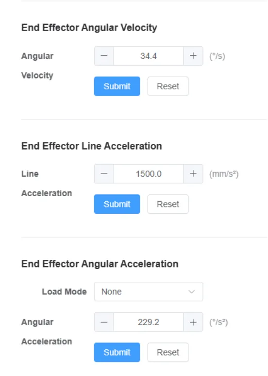
6.8.2 End Effector Speed Settings
This is an advanced parameter setting interface for fine-tuning the motion performance of the robotic arm's end effector. It allows users to set the upper limits of speed and acceleration for the movement of the end effector tool in accordance with specific process tasks and safety requirements.
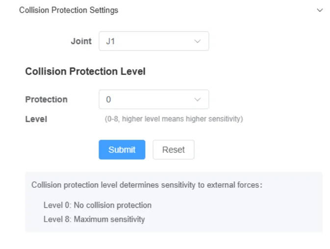
6.8.3 Collision Protection Settings
This is a collision safety sensitivity adjustment panel, used to set the level of each robotic arm joint in response to collisions or abnormal resistance. When the robotic arm experiences an accidental collision or encounters excessive resistance, the system will detect the incident in a timely manner and trigger an emergency stop according to the preset level, thus protecting personnel safety and preventing equipment damage.
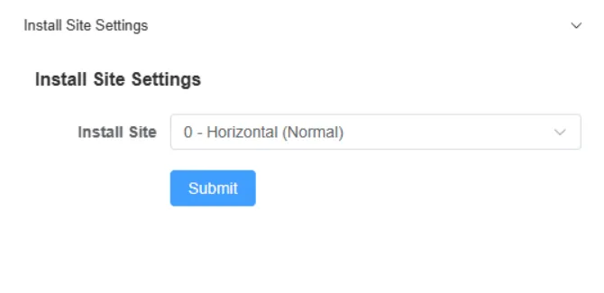
6.8.4 Mounting Position Settings
This interface is used to set the physical mounting posture of the robotic arm body, which serves as a fundamental step for the robotic arm's coordinate system calibration. Its results directly affect the robotic arm's motion control logic and spatial coordinate calculation. Users can select vertical mounting, horizontal mounting, and inverted mounting according to actual application scenarios.
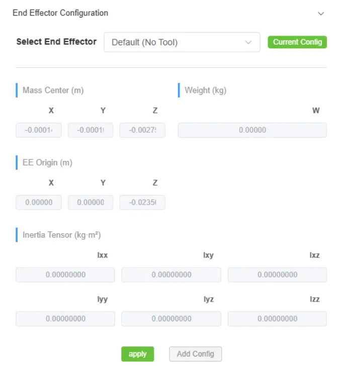
6.8.5 End Effector Configuration
This interface is used for parameter calibration of the robotic arm's end effector tool, which serves to precisely define the physical properties of the tool mounted on the end effector. This enables the robotic arm control system to accurately calculate the tool's parameters, such as mass, center of gravity, and dimensions, thereby achieving precise motion control and torque compensation
7 Configuration
7.1 Ethernet Port Settings
This module provides users with the function of configuring core parameters for network connections. By manually setting the device's network protocol and other relevant parameters, it enables the device to achieve network identity identification, route addressing, and domain name resolution, ensuring that the device can access the target network normally and conduct data communication with other devices or servers in the network.
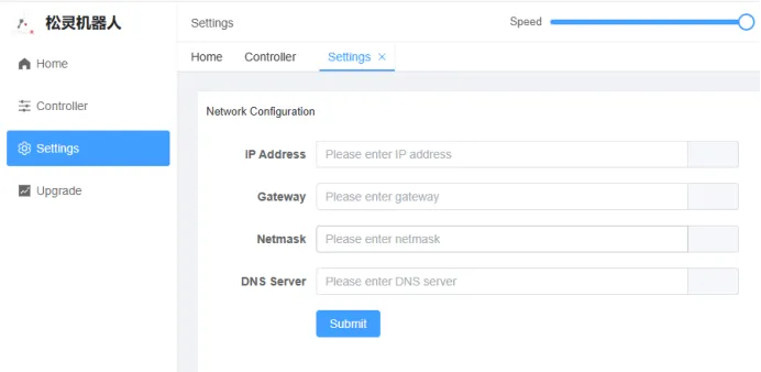
After manually setting the ip address of the robotic arm, you can connect the robotic arm and the host computer via the Ethernet port. Ensuring that the host computer and the robotic arm are on the same network segment will enable successful communication between them.
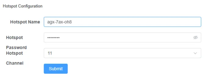
7.2 Hotspot Settings
This interface is used to configure the basic network parameters for the robotic arm to act as a Wi-Fi hotspot, enabling other devices(mobile devices)to connect to it via Wi-Fi and realize wireless data transmission and control functions.
8 Upgrade
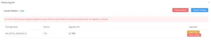
8.1 Software Upgrade
This module provides the robotic arm with software version management and system upgrade capabilities, and supports functions including firmware version query, system update, and soft restart.
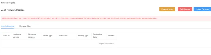
8.2 Firmware Upgrade
This module provides a firmware upgrade function for the robotic arm's joint modules. It also supports features including joint information monitoring and joint hardware version query, which ensures the reliability of the firmware upgrade process and system compatibility of the joint modules.
Note: When upgrading the firmware, you must first click the Upgrade Mode button to enter the upgrade mode, then perform the joint firmware upgrade. The robotic arm will be disabled during the upgrade. Ensure the robotic arm is placed in a safe posture. After the firmware upgrade of all joint modules is completed, you must click the Exit Upgrade button. Otherwise, the robotic arm will be unavailable for use.
9 Secondary Development
You need to get a Python-based API interface for the secondary development of the robotic arm currently provided. Only links are provided here; for detailed secondary development of the robotic arm, please refer to the GitHub link.
Before using the sdk, please go to the web page and enable the CAN publishing.
|
|
|
|
|
10 Robotic Arm CAN Protocol
The robotic arm provides a CAN interface for users'development, and users can perform command control on the robotic arm via this interface.
The CAN communication standard adopted by the robotic arm is CAN 2.0B, with a communication baud rate of 1000k and the message format following the MOTOROLA(MSB) format.
If you need to develop with CAN commands, please contact AgileX Robotics Support Tea to obtain the CAN Protocol Manual.
11 Maintenance and Servicing
To ensure the robotic arm maintains high performance for an extended period, regular maintenance must be performed. All maintenance and servicing operations must strictly comply with all instructions specified in this manual. The purpose of maintenance and servicing is to ensure the normal operation of the robotic arm and its accessories.
11.1 Storage Notes
After use, perform a zero position calibration before powering off and storing the robotic arm. Tidy up and organize all wire harnesses to avoid entanglement or excessive pulling.
Operating and Storage Environmental Requirements: Temperature:-20 to 50 ℃, Humidity:25% to 85% non-condensing.
11.2 Servicing Notes
Maintenance and servicing must be performed when the robotic arm is in a zero-reset and power-off state. After powering-off, perform the following operations:
Note: Robotic Arm Cleaning: Use wet wipes or dry rags dampened with water to remove dust, dirt, and oil stains from the robotic arm.Motor Inspection: Check for damage or deformation of the motor and its structural components.Cable Inspection: Check for the security of power cables and CAN cables, and any damage to their outer sheaths.
11.3 Emergency Handling
In case of an emergency, you can unplug the aviation connector directly to cut off the power supply. Note that the robotic arm will be deactivated and drop directly after power-off. Take extreme care to prevent damage to the robotic arm, as well as harm to the surrounding environment and personnel. Power off by unplugging the connector is an emergency response measure only, and is not intended to prevent injury.
Appendix: Dimension Drawings
1 Robotic Arm Dimensions
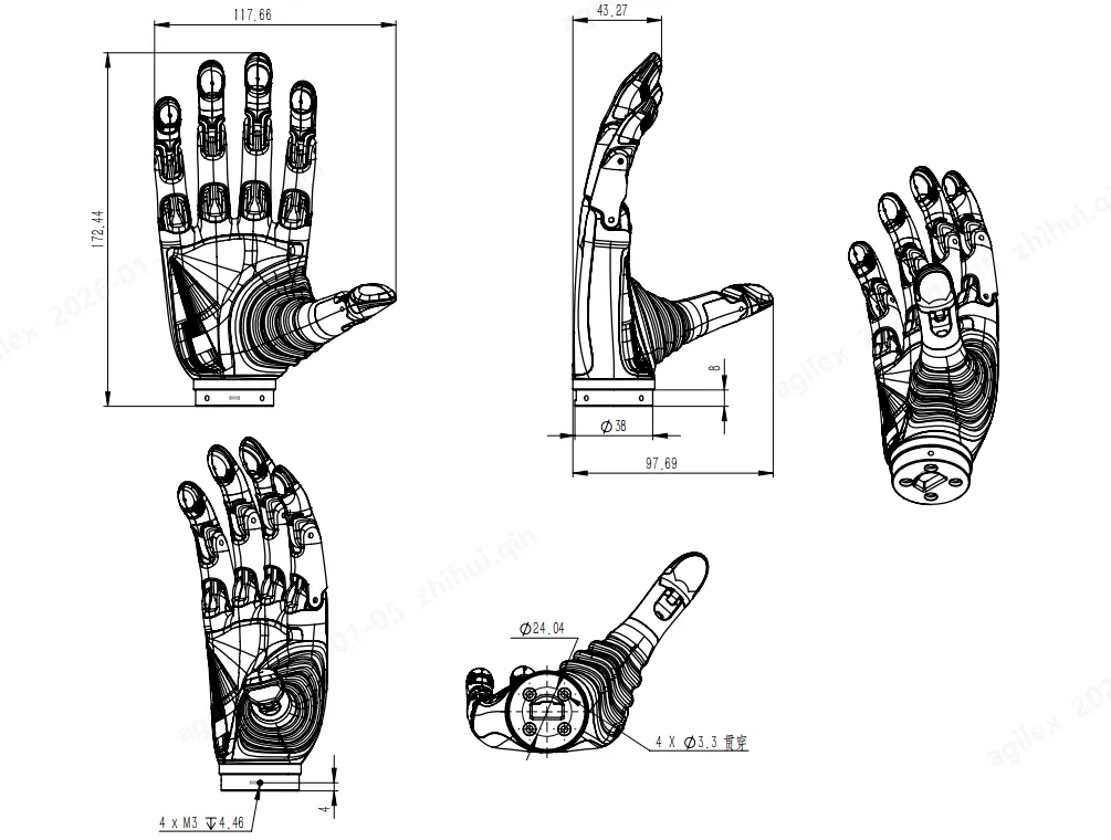
2 Robotic Arm with Dexterous Hand
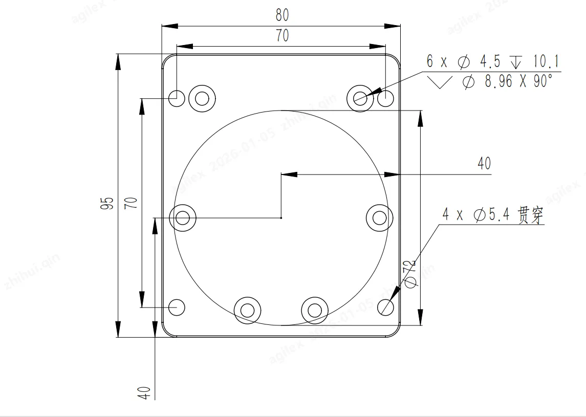
3 Base
4 Dexterous Hand Diagram
5 Dexterous Hand Flange Mounting Diagram